


Choosing
between a multi-band EFHW and a single band OCFD vertical
Last Month I reported that my 40m long 80m EFHW was really
convenient in that it allowed me to operate on all HF bands but suffered from
“nulls” in its propagation patterns. I have been gathering bits to make my own
cobweb and then along came December’s Radcom article (2023) about a Halfwave
Vertical antenna fed off centre (OCFV) to give good gain without
needing those tiresome radials. Tim Hier, M5TM wrote the article on pages 18-20.
It covers a single band antenna but it is easy to build – if you have a suitable
fishing pole and a transformer plus a couple of chokes.
I don’t have room for radials in the corner of the garden
that I operate from otherwise I would have built a DXCommander vertical, Callum
has all the constructional details on his web site http://M0MCX.co.uk or http://DXCommander.com You do need to lay down maybe 16 radials on
the ground for it, each maybe 12 to 16 feet long. I do recommend trying this
antenna if you do have room for radials, but I don’t.
Back to the OCFV that needs no radials. I began my ham
radio using a halfwave CB antenna shortened a bit for 10m and had been able to
tune it up on all bands from 20m and up and got good use out of it, when it was
nearly forty feet of the ground and I also had good experience with my 20m long
horizontal Offset Centre fed dipole (OCFD) for 40m and its odd harmonics that I
reported in CONTACT in April, 2020.
One question not answered in Tim’s December article was
what effect raising the base of the vertical would have. This is not easy to do
with a conventional vertical because of the need for radials – either a large set
of untuned radials lying on the ground or a small set of tuned radials elevated
along with the base but a halfwave vertical does not need radials and can be
raised easily. Tim only discusses using his vertical low to the ground (28cm)
so I wondered how it would fare if raised high up.
How to choose what height was best? I have a two story
garage with its apex at 20 feet so it is relatively easy for me to get above 7
or 8 metres of height, I have two or three old aluminium sailing masts that are
25 feet long and I often lash 38mm thick broomsticks to these to get me near
10m so gaining height is not too much of a problem.
Ordinary half wave long dipoles have an impedance of 50 to
70 Ohms at their centre, depending on height, but the patterns of current and
voltage as you move away from the centre are such that you can pick any
impedance you want. Windom antennas use this by going to a point 33% along the
half wavelength long wire to give 200 Ohms and use a 4:1 impedance transformer,
(a 2:1 Voltage transformer, i.e with a turns ration of 2:1 ) this will convert 200
Ohms to 50 (if you wire it the right way around!).
Tim opted for a 14% feed point and this gives 450 Ohms and
therefore needs a 9:1 impedance transformer (3:1 voltage or turns ratio). This was a good starting point and Tim’s
article describes the appropriate lengths needed, he notes that real life gave
him lengths 7.4% less than theory and you must always expect some
experimentation when building real antennas, unless you can get into outer
space and use infinitely thin wire that is a perfect conductor.
One thing Tim does not stress (although he does mention it)
is that you must use chokes when feeding unbalanced antennas, best practice is
to have a choke right at the transformer unlike an EFHW which needs a choke 8
feet (1/20th wavelength) or so down the feeder and a second choke
down the feedline, where your coax cable enters your shack.
If you omit these chokes the antenna will work. Antennas always
work but there may be strange goings on in your shack that go un-noticed but
affect performance. A raised noise level and a susceptibility to interference
or you may generate interference that creates problems in your shack, or worse,
creates problems outside your shack. It is not good to activate your neighbours
burglar alarm or coffee machine every time you transmit. It is not good to have
your neighbour’s Wifi drop put either, even if no-one notices.
So, Tim covers the practical aspects of making it but only
gives results for one particular height. How does the OCFV
behave at different heights.
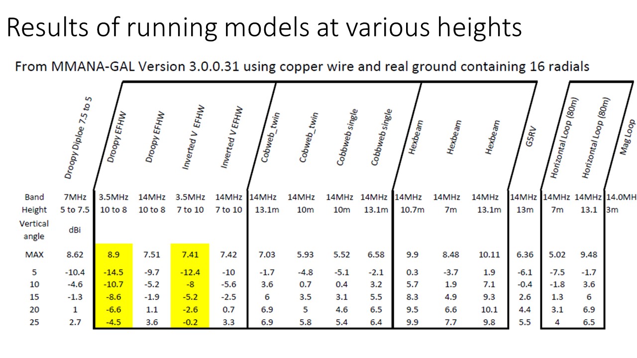
MMANA-Gal is a free antenna
modelling package that can plot propagation patterns and compute SWRs across
different frequencies, you can vary the height of an antenna and try different
ground configurations. Here I just use it at different heights. I covered its
use in CONTACT March, 2020.
When a signal leaves an antenna it matters what the vertical
angle pattern is. If you have a 100W transmitter and the antenna’s peak output
is straight up in the air you will not get very far. The signal might bounce
back to Earth if the operating frequency is in the right range of frequencies
(below the maximum useable frequency for the particular take-off angle) and
high enough so that the D layer does not absorb it.
If it does bounce back you will be able to talk to people
in Northern Ireland and maybe the Republic of Ireland, and the rest of the UK.
It is described as “cloud warmer” and an antenna with NVIS properties. (Near
Vertical Incidence Skywave).
When the peak is between 5 and 10 degrees off the horizon
you can expect a radio wave in the correct range of frequencies to bounce off
the F layers and give you a contact quite far away, if the angle is 45 degrees
then not so far away. If you have a directional antenna, horizontally and/or
vertically you need to work out who do you want to talk to, or at least who are
you most likely to talk to, where does your strongest signal land.
For DX contacts we want very low angles but not zero,
unless your terrain falls away significantly. We typically look at the 5
degrees take-off angle. Of course to cover all areas up to the furthest DX you
can work we need some energy to go out on all the different angles so you want
a response that is not too tightly focussed.
It is a compromise. A tightly focussed beam gives you gain,
more of your 100W goes in that direction but less in other directions, you pick
up strong stations from the bigger lobes of your antenna pattern and weaker
signals from the smaller lobes of the pattern. Transmit and receive paths are
essentially identical, although some receive antennas have more noise. A
tightly focussed beam suits particular distances, if you want to talk to all
stations up to that distance you need a pattern with energies from 50 degrees
down to 5 degrees. It is the same problem as the horizontal pattern of lobes,
peaks and nulls. It depends who you want to talk to, or how many people you
want to talk to.
Working out what angle gives what distance is an interesting
exercise in mathematics, about A-level standard. I will write another short
article about that or see my blog.

Figure 1 Distance reached by various Take off
angles, for differing F layer heights
As you can see the distance reached depends on what is
called the virtual height of the ionosphere. For a layer height of 150 miles,
you’ll get over 1,600 miles at 5 degrees, 1200 miles at 10 degrees and only 200
miles at 45 degrees. Of course what really happens is that you reach all these
stations but you are much stronger at 1,600 miles than 300 miles.
It is hard to read the graph’s horizontal scale so I decided
to work out my own spreadsheet, it’s on my blog http://MI5AFL.Blogspot.com and
how I derived it is in another article.
Back to the OCFV; Tim
gives a MMANA-GAL design in the article and I modified this slightly; Remember
that MMANA-GAL is quite simple to use, the main screen has four tabs,
“Geometry”, “View”, “Calculate” and “Far field Plots”. Figure 2 give the
contents of the Geometry tab

If you want to paste the file in figure 3 into a text
editor and save is as OCFV.maa you can run your own copy of MMANA-Gal on
it. (or download it from my blog )

This antenna is placed on the ground (wire 1’s Z1 value is
zero) – in real life you should lift it even a bit. Tim had his 28cm up. Better
is 0.5m as a minimum. You can specify a height correction on the “Calculate”
tab before starting the analysis. I did this for a range of heights to see what
changed and plotted the table below. The first column gives the height of the
base of the vertical and the 5th column gives the gain at a take-off
angle of five degrees.
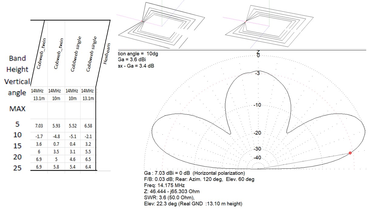
Interestingly at about 7m you get two lobes, as seen in
figure 5 below. The secondary lobe is at a lower angle and is better for DX. I
asked MMANA-Gal to calculate the gain at maximum, (or the two maximums once the
height exceeded 7m and also the gain at 10 degrees and 5 degrees from the
horizon.
I also noted the SWR and the actual impedance, in practice
these don’t matter too much, they are low enough to not need matching beyond
the 9:1 transformer at the feed point. Do arrange the feedline to sit at a big
angle from the wire (greater than 45 degrees) for maybe ten feet or more and as
I said above do add at least one choke down the coax, preferably two. The
chokes could be 12 to 14 turns of coax would around an FT240-43 or FT240-31.
Alternatively run 450 Ohm twin-lead back to the shack and
convert it there. I have a balanced ATU (MFJ-974B) as well as a conventional
MFJ-969 so I may experiment with both options.
|
OCFV at different
heights from RADCOM Dec 2023, Tim M5TM design, modelling (different heights)
by Ian MI5AFL |
|||||||
|
Height/m |
Max gain |
Angle |
Gain10® |
Gain5® |
SWR |
Real Z |
Imag Z |
|
0.0 |
0.20 |
20.00 |
-1.40 |
-5.10 |
6.50 |
773 |
1229 |
|
0.5 |
0.40 |
18.40 |
-1.00 |
-4.70 |
1.14 |
506 |
-30 |
|
1.0 |
0.50 |
17.50 |
0.00 |
-4.30 |
1.10 |
464 |
-44 |
|
2.0 |
0.90 |
16.00 |
0.00 |
-3.50 |
1.10 |
417 |
-33 |
|
2.5 |
1.00 |
15.40 |
0.20 |
-3.20 |
1.10 |
406 |
-20 |
|
3.0 |
1.20 |
14.90 |
0.40 |
-2.90 |
1.13 |
400 |
-8 |
|
4.00 |
1.30 |
14.00 |
0.70 |
-2.50 |
1.10 |
404 |
13 |
|
5.00 |
1.30 |
13.30 |
0.90 |
-2.20 |
1.10 |
417 |
22 |
|
6.00 |
1.30 |
12.70 |
1.00 |
-1.90 |
1.1 |
429 |
20 |
|
7.00 |
1.60 |
40.60 |
Note for the secondary
peak at a lower angle see the line below |
||||
|
1.30 |
12.00 |
1.10 |
-1.70 |
1 |
434 |
13 |
|
|
8.00 |
2.10 |
37.80 |
Note for the secondary
peak at a lower angle see the line below |
||||
|
1.50 |
11.00 |
1.40 |
-1.30 |
1 |
434 |
5 |
|
|
9.00 |
2.40 |
34.00 |
Note for the secondary
peak at a lower angle see the line below |
||||
|
1.70 |
11.00 |
1.60 |
-0.90 |
1 |
429 |
1 |
|
|
10.00 |
2.60 |
31.00 |
Note for the secondary
peak at a lower angle see the line below |
||||
|
2.00 |
11.00 |
1.90 |
-0.50 |
1.1 |
424 |
1 |
|
Table
1: Table of relative gains at different heights at the maximum and at 5 and 10
degrees
Things to note from table 1. The important figures are highlighted
in yellow, underlined and in italics,
At a height of 0.5m off the ground
the maximum gain is 0.4 dB and the gain at 5 degrees of take-off angle is -4.70db. We could use
dBi here but the important thing is the difference in dB between different
arrangements of the antenna.
At a height of 7m off the ground the
maximum gain is 1.3 dB and the gain at 5 degrees of take-off angle is -1.70db.
In other words, at 7m there is 3dB more energy going out at
five degrees, twice as much power for working long distance DX. To be sure 3dB
is only half an S point, but it is an important half S point. It turns a 100W
radio into a 200W radio! It is also better than the 0.5m configuration from 30
to 50 degrees (the second lobe up in figure 5 below)
|
Figure 4
Vertical Pattern at 0.5 Metres |


Results will not be the same with a quarter wave vertical
as the role of the radials is very important. You could use raised tuned
radials, this is a different antenna.
You can get MMANA-Gal from the download button at http://gal-ana.de/basicmm/en/
And you can get the design files via my blog at https://MI5AFL.blogspot.com
Now to build it and compare it to my EFHW on 17m. I still
want to build a cobweb as it is a multiband omnidirectional antenna for all
bands from 20m and up and I will still need the EFHW for 40m and 80m.
P.S. After writing this whilst on holiday I came home to
discover Tim had written another article in February’s RADCOM, He was exploring
a single band delta loop and comparing it to a vertical and he has some of the
height modelling in his article. I have covered a larger range of heights in
Table 1 above as suits my own installation. He makes a strong case for using a
Delta but I personally prefer an OCFV because of its simplicity and
small footprint. Read both carefully and decide for yourself.
Any antenna works, what makes one better? Many factors
matter, not just technical parameters. Cost, convenience, easy of making, ease
of installation, robustness and longevity matter to.
73 de Ian / MI5AFL