I am building a WSPR transmitter, copying the work of the Sprat article by Paul Taylor, VK3HN where he also referenced his own blog at https://vk3hn.wordpress.com/2021/10/01/20-meters-200mw-12000-miles-wspr-magic/?wref=tp and software at https://github.com/prt459/WSPR_GPS_BEACON. The blog entry has a 8 minute Youtube video that succinctly covers the complete project. I only cover the amplifier and low pass filter in this post.
I currently have three bought modules feeding the circuit below. The modules are a Arduino Nano, a Si5351 VFO module and a Neo6M UBlox GPS. I also have a 16 character by 2 line LCD display. The output of the Si5351 is less than 7dbM and is a square wave, I need to increase its strength and filter out the harmonics.
Paul copied his amplifier from part of fig 12.32 in the EMRFD book, he omitted the inter-stage 2k2 resistor - the one in parallel with the capacitor below. (all capacitors below are 0.1uF by the way)
There is no 2k2 across the third capacitor from the left...
I will probably put a heatsink on the 2N3866, whether it needs it or not depends on how continuous the WSPR signals transmissions are.
I connected up a dummy load (actually a 10W 40dB attenuator) and a signal generator and power supply.
I suppose a lot of articles appear whiter than white and seem perfect... let me tell you the reality and what happened when I tested the board above. I applied 12V from my current limited power supply and with no RF input measured the voltage across the emitter resistors - The DC bias ones, the 220 and 22 Ohm ones. I got a reading of roughly a volt across Q1 and Q2s resistors but noted I was taking a lot of current from the power supply - a quarter amp and Q2 was getting hot.
I lifted the 22 Ohm series resistor in the collector circuit of Q2 up in the air so Q2 got no current.
I then applied RF and got no output from the transformer on Q1's collector. Two problems!
<sigh> when winding a bifilar transformer and you need to connect the end of one wiring to the start of another, you have a 50% chance of getting it right unless you use a continuity meter to identify winding 1 and winding 2. I had got Q1's transformer wrong and accidentality got Q2's correct.
That one was easily fixed, the second transformer tested out ok for continuity so I wondered if the transistor was ok, I had drawn a lot of current and it is always bad when you smell the heat. I desoldered Q2 and checked it on my GM328 component tester (reviewed in October, 2021 CONTACT) It identified a beta of 98 and a VBE of 450mV (bit low but if there is beta gain I suppose it is working) It also identified the transistor pinout (and that it as an NPN) Oops, I had got the pinout wrong. Soldering it back, the right way around and adding a heatsink for good measure gave better results. It was working.
Q2 is a manufacturer badged 2N3866 that the GQRP club "sell" - they actually give them away free of you buy anything else from them. Do join the GQRP club, it costs £6 per year. https://www.gqrp.com/join.htm
Once it was working, I noted that the power supply was supplying 12 mA with no signal and 56 mA with 500mV applied.
Applying a half volt from a signal generator gave the following grotty waveform and its spectrum.
A peak to peak of nearly 8 volts. This is a peak voltage of 4 and an RMS value of 4 times 0.7 or 2.8 Volts. Power is voltage squared divided by R or (2.8 * 2.8)/50 or 157mW. Although scopes are only accurate to maybe 3% or so...
The spectrum is through a 40dB attenuator so the fundamental is actually 22dBm (160mW), the third harmonic is only 12dB below the fundamental and you see the classic spectrum of a square wave. (fundamental and the odd harmonics)
A low pass filter would extract the fundamental as a nice clean sinewave and reject all the other distorting harmonics.
I built a 40m Lowpass filter in the February 2022 edition of contact, here is a photograph;
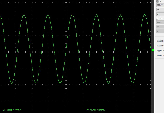
and here is two waveforms showing the oscilloscope and spectrum analyser waveforms on the output.
The harmonics are in the noise, Although showing as 40dB below the fundamental they are probably below that and represent signals of one hundredth of a milliwatt!
( https://www.rapidtables.com/convert/power/dBm_to_mW.html shows -20dBm as 0.01mW )
The output is still a healthy +21.5dBm (allowing foe the 40dB attenuator) and this is 141mW
I'll show you the actual outputs from the entire WSPR system next month D.V.


x10%20probes.jpg)


